cx
A Study of the Functional Ecology and Mechanical Properties of Hooks in Nature
Submitted by
Bruce Edward Saunders
July 2004
University of Bath
Centre for Biomimetic and Natural Technologies
Department of Mechanical Engineering
Faculty of Engineering and Design
BA2 7AY
Supervisor: Dr. A Bowyer
Research Funded by the Engineering and Physical Sciences Research Council (EPSRC)
Project no. EN042
Summary
This report contains the results of my investigations into:
The functional ecology and the mechanical properties of hook-shaped biological structures.
It has four parts: a literature review, two case studies and a final concluding section.
The literature review contains the results of research that I conducted into biological references, gathering information on organisms with hooked attachment mechanisms as well discussions on the issues of mimicking biological structures for engineers, their potential benefits and the difficulties. It contains my background research into the current manufacture and design of hooks in engineering and an explanation of biological terms such as functional ecology.
The first case study is the result of a preliminary investigation into the functional ecology of bird claws. It took the form of 2-D digitising of a hook outline and considering a functional ecological hypothesis.
The second case study is a study of the mechanical properties of burdock and other hooks. The first experiment was conducted into the gathering of an accurate 3-D image of a burdock hook, a bee tarsus and a grasshopper tarsus. The specimens were imaged using a single-photon confocal microscope in the Biology department,
The second experiment was the measurement of the fracture forces of a burdock hook. An attempt was made to identify a dominant dimension that influenced the hook’s fracture force in a critical fashion whilst incorporating knowledge of the local environment and activities of the hook to develop a functional ecological hypothesis.
The report concludes with an integration of the three experiments into a process for producing hooks made of a composite analogue of a biological material, optimally designed by evolution (ideally) for specific functions. This includes a method of directly measuring small shapes using a confocal microscope, transferring this data to a finite element package and onwards to a rapid prototyping machine.
ACKNOWLEDGEMENT
For my mother and father, Jean and Alan Saunders.
Dedicated to Simon Lee, Siobhan Paterson, Ursula Vermeulen, James Phillips and other friends I left behind, who are no longer with us and whose absence reminds me to be grateful for the opportunities I have, to do more.
Contents
SECTION I – Introduction, Literature Review, Generating Ideas. 8
2.1 Glossary and General Biological Background Material 11
2.2 Two Methods of Classifying Hooks 13
2.3 Classification by Morphology – Nachtigall 13
2.3.1 Rigid and Permanent Attachments 13
2.3.2 Releasable attachments of two matchng structures 17
2.3.3 Releasable attachements by one structure 22
2.4 Classification by Function – Gorb 32
2.6 Discussion of an Application of Functional Ecology 35
3 The mechanical design of hooks 37
3.1.2 Probablistic Fasteners 38
3.1.3 The Operation of the Dragonfly Mechanism 38
Section I I – Case Study 1: A Study of Bird Claws 42
4 The Two Dimensional Digitising of Biological Structures 43
4.2 Systematic Biology and Finding a Function Through the Digitised Profile 43
4.4 The Digitising of a Tiger’s Claw 45
4.5 Experiment 1.1 : Bird Claw Profiles 45
Section III – Case Study 2: A Study of Burdock (Arctium lappa) 49
5 Imaging and Fracture Forces 50
5.1.3 The Review of Imaging methods 51
6 TRIZ: An Investigation into a Dynamic Hook 52
6.1.2 Shape Memory Materials 52
7.2.1 Specimen Orientation (microscopy technique) 54
7.4.3 Accuracy in measurement 59
8 Experiment 2.2 – Burdock – Testing the fracture force of the hook 62
8.3.1 The fracture loads of specimen hooks 66
Section IV – Final Discussion and Conclusions 69
9 Report Discussion and Conclusions 70
9.1 Experiments 1.1, 2.1 and 2.2 70
9.1.1 Case Study 1 – Bird Claws 70
9.1.2 Case study 2 – Burdock 70
10.2 Web Literature References 74
The procedure to obtain the profile shape of the talons using Nih image software. 76
Navigating around the image 76
Setting the measurement scale 76
Image Processing, Analysis and Machine Vision, Milan Sonka, Vaclav Hlavac, Roger Boyle [22] 78
Results to Experiment 1.1, the 2-D digitising of robin and thrush talons 79
Table of Figures
Figure 1 – SEM of a burdock (Arctium minus) hook at the tip of a modified bract. 8
Figure 3 A – Miter joints between basal and lateral plates of balanids, 15
Figure 5 – Hydroporous ferrugineus (Nachtigall p16) 16
Figure 9 – (Nachtigall p35) 19
Figure 9 – Snap-type connection in Sepia officinalis (Nachtigall p38) 20
Figure 10 – Tentacular fasteners (Nachtigall p38) 20
Figure 11 – Squid Abralia [V] 21
Figure 12 – Squid Onychoteuthis [VI] 21
Figure 13 – Squid Galiteuthis glacialis [VI] 21
Figure 14 – Squid Galiteuthis glacialis 21
Figure 15 – Radolaria (Nachtigall p42) 22
Figure 16 – Antenna cleaning apparatus of honey bee (Apis mellifera) (Nachtigall p38) 22
Figure 19 – Wing connections jungate (A) and frenate (B) (Nachtigall p61) 24
Figure 21 – Manduca sexta (Hawkmoth) in flight [VII] 25
Figure 22 – Shield bug Palomena [VIII] 25
Figure 23 – mating shield bugs Graphosoma [IX] 25
Figure 24 –pale cotton stainer bug Pyrrhocridae: Dysdercus sidae [X] 25
Figure 25 – water strider Gerridae [XI] 25
Figure 26 – female cicada T.pruinosa [XII] 26
Figure 27 – Scorpion fly (Mecoptera panorpidae) [XIII] 26
Figure 28 – Oncomiracidium (drawing) [XIV] 26
Figure 29 – fishlouse Branchiuran crustacean (also see Figure 2) [XV] 26
Figure 30 – Gnathia maxilaris [XVI] 27
Figure 31 – Woodpecker tongue showing keratinised teeth [XVII] 27
Figure 32 – Plectocomia himilayana showing climbing spines [XVIII] 28
Figure 33 – Uncaria with the red arrow indicating typical hook position [XIX] 28
Figure 34 – tapeworm trypanorhyncha lascisthynchus [XX] 29
Figure 35 – Burdock Arctium lappa [XXI] 29
Figure 36 – A. eupatoria [XXII] 29
Figure 37 – Bedstraw Galium [XXIII] 30
Figure 38 – Echinorhynchus salmoides acanthocephalan worm [XXIV] 30
Figure 41 – Wing inter-lock devices in Heteroptera and Auchenorrhyncha (Gorb p45) 34
Figure 42 – Diagram showing prominent dimensions and sections of a manufactured hook 37
Figure 44 – Dragonfly Head-arresting mechanism taken from [10]) 39
Figure 45 A dimensionless plot of the attachment device design space from [11] p170) 40
Figure 46 – Dragonfly head-arresting mechanism – detached 40
Figure 47 – Dragonfly Head-arresting mechanism – attached 41
Figure 48 – Result of digitising Robin Claw and exporting data to Excel 46
Figure 49 – Result of digitising Thrush Claw and exporting data to Excel 47
Figure 50 – velcro, from [17] 50
Figure 51 – SEM of burdock hook (a reproduction of Figure 1) 50
Figure 52 – A specimen of Burdock 54
Figure 53 – Sterogram 1 of the burdock hook specimen 55
Figure 54 – Stereogram 2 of the burdock hook specimen 55
Figure 55 – Stereogram 3 of the burdock hook specimen 56
Figure 56 – 1 – 28 confocal microscope image “slices” of hooked bee tarsus 57
Figure 57 – 1-30 consecutive confocal microscope image “slices” of the hooked grasshopper tarsus 59
Figure 58 – One of the burdock bushes from which samples were collected 62
Figure 59 – mounting the bracts for testing 63
Figure 61 – SEM’s of the fractured hooks 65
Table 2 : Fracture forces of burdock hooks 66
Figure 62 – Specimens 2 – 7, Mean hook fracture forces vs Burdock fruit diameter 67
Table 3 – Specimens 2-7 mean hook fracture forces and dimensions of whole burdock fruit 67
SECTION I – Introduction, Literature Review, Generating Ideas.
Figure 1 – SEM of a burdock (Arctium minus) hook at the tip of a modified bract.
Learning about the background science and the biology from which the research proposal arose has occupied much time. The Museum of Natural History in London has been visited for viewing of the fossils of the Archeopterix as well as the Smithsonian Institute in Washington DC where fossils from the Burgess Shale in Canada have been observed. Some fundamental zoology was explored consisting of collecting insects and observing bird-life in South Africa.
These have all formed part of the research trail that originates from the author of the proposal, Dr Andrew Parker. Thus it is appropriate to introduce an early discussion of his book since it provides an evolutionary context as well as a model for this research.
Throughout this research project this researcher has been dogged by the suggestion that the end goal should have commercial application. From the hypothesis you, the reader, will see that indeed there is the possibility of developing a system for eventual commercial use. However it is not thought at this stage that some marvellous new form of hook will present itself for patenting. Instead the hypothesis will propose a method of using biological information to develop a design system to aid designers to manufacture light and efficient hooks from composite materials.
1.1“In a Blink of an Eye: the Cause of the Most Dramatic Event in the History of Life” by Dr Andrew Parker [8]
Dr Parker’s book discusses the “Cambrian Explosion”, so-called because it was during the Cambrian period of the earth’s development that the diversity of life on earth exploded in numbers and differentiation between organisms increased greatly.
Dr Parker expresses the view that it was the development of vision and the change from a blind world to a world of organisms that could see that led to organisms responding to the change by developing armour, limbs, mating patterns, defence mechanisms, colour and more, in a period of time (5 million years by his estimation) that is relatively short in the history of the world.
It is his book that unlocks the secret behind the research proposal: “The functional ecology and mechanical properties of hooks”. Dr Parker’s book could have an alternative title: “The functional ecology and physical properties of vision”. He discusses the development of vision and the different forms of vision systems that organisms employ as well as the effects of colour. There are five fundamental types of eyes which employ different physical principles in order to perform the common function, seeing. These types of eyes evolved into different species at different times on the evolutionary time-scale. Some types of eyes occur in completely different species yet still obey the same physical principles, such as the eye of the octopus and the human eye.
Considering the grand set of all hooks in nature in this way, one is granted an insight into the development of a study of the vast number of occurrences of hooks in nature. The study of the mechanical properties of a hook is of biological interest since when placed in a functional ecological context the research should reveal information about the biological system in which it participated.
The interest in biological hook-shaped structures to engineers has two main commercial applications:
-
Composite hooks imitating properties of those of biological materials, and
-
The study of micro-fabrication methods.
-
Biomedical/micro-surgical applications.
A study of a natural hook in its environment and an observation of its properties and performance can provide indicators for a design engineer when considering the design and manufacture of a hook.
Hooks constructed of composite materials have advantages. Composites are used for their high strength and reduced mass and research is well advanced into replacing parts that might ordinarily be made from dense metallic materials by composite parts (for example, in car engines).
The application to micro-fabrication techniques arises from scale effects that have been observed in structures as they decrease in size. To illustrate, if one takes a cube of material on a surface and reduces its size proportionally while observing the effects on mass (a function of gravity) and adhesion (a function of area), one finds that the gravitational force on the cube (its weight) reduces faster (of the order of 1/6th faster) than adhesive forces (friction between the cube and surface).
Combine this behaviour with current manufacturing research techniques into MEM’s (micro-electric mechanical devices) and surface texturing and there appears reason for studying small (micro) attachment mechanisms as they occur naturally in nature. Here we have an opportunity to study real-life models of systems whose behaviour becomes more difficult to imitate and predict as size decreases. (This is discussed in Section 2.8)
I compare the study of the forces on microstructures that are often designed to utilise friction and other small forces to the study of fluid mechanics.
In fluid mechanics, the flow field behaviour is artificially split into different realms for study, the fluid behaviour being dominated by different forms of the energy equation. Boundary layer flows (the study of fluid behaviour close to a surface) and thin, “squeezed” lubricant films are described by the same energy equation that is used to describe super-sonic flows, even although these different types of flows are different in terms of relative component energy exchanges.
High speed, high energy flows are dominated by large kinetic energy terms. Low speed flows have larger potential energy and friction terms relative to kinetic energy such that they cannot be ignored in the calculations of energy exchange.
Likewise with regard to mechanical structures but with reference to size, as the size of a structure reduces so the impact of forces that can normally be ignored increases (i.e. scaling effects) Small structures and their behaviour can provide a starting point for the design engineer and provide an insight into the behaviours of the structures at the order of size at which he wishes to design.
In the case of microstructures, biological structures and their behaviour can provide a starting point for the design engineer and provide an insight into the behaviours of the structures at the order of size with which he wishes to design.
The mechanical properties of a hook are therefore defined by its basic component materials and its size, while the function (i.e. purpose) and shape are a function of the material, size and environmental factors. The environmental factors are the substrate in which it engages and other “outside” influences. With regard to the manufacture of the micro-sized hook, this is a further interesting field. The science of micro-fabrication in its current state does not completely provide for the manufacture of biomimetic structures. I believe that the future of the science requires a greater understanding of self-assembly, the science of growing structures in bioreactors to mimic the behaviour of natural structures as closely as possible.
2The Hypothesis
2.1.1Definition and Description
Hook Fundamental:
Consider the set of all hooks in nature. This set can be divided into subsets of similar hooks that I choose to describe as the hook fundamentals, F1-n. Each hook fundamental Fi is defined by a characteristic material and function. It is the presence of environmental factors such as the substrate to which the hook is to attached and other properties of the organism from which it arises that the hook gains a characteristic shape.
Some examples of hook fundamentals:
-
The set of plant hooks for attachment (of cellulose)
-
The set of bird claws (of keratin)
-
The set of insect tarsii (insect cuticle)
-
The set of insect mandibles (insect cuticle)
-
The set of feline claws (of keratin)
In the first instance consideration has been restricted to those examples of hooks that interact with a substrate i.e. they have adapted for a function other than the interaction of parts of the same organism or organisms of the same type as in the mating systems between male and female parts.
Not all component materials (which are biological composites) within a set of hooks will necessarily be identical, for example there may exist trace elements in the material or there may be differences in fibre alignment that in some way augment the strength or performance of the hook.
Establishing relationships between two hooks within a fundamental group:
Let there be types of hook f 1-n, from n different species, that are members of a fundamental group Fi, defined by the component material and function.
Each hook fi in the set Fi will have evolved to its current shape through the properties of the component material and its function as well as external system factors to give a characteristic shape.
There are two methods of assessing hook fi’s performance:
-
The first is to assess the ultimate failure strength of the hook in a laboratory environment using an Instron testing machine or some other engineering tensile tester.
-
The second is to test a hook in a system that replicates the natural system as closely as possible. For instance, a burdock hook would be tested using natural fur as a substrate because this is the natural dispersal mechanism of the burdock seed pod.
Using both of the above methods on samples of a hook specimen f i and assessing the differences between the results gives an insight into the magnitude of forces that can only be measured by inference, such as those due to friction (a function of material and surface textures).
This then provides us with a method of assessing the frictional forces and other scaling forces and their contribution to attachment in the hook f i.
We can then repeat similar tests on the hook specimen f j.
The performance of the n hooks can be plotted on the graph of size versus strength implying that function and material have thus been linearised. A line can then be drawn between them to represent a transition between their relative performances.
This line should represent a continuous transition between the group of hooks and under normal conditions it should be predictable by taking into account the scaling relationship mentioned in the introduction and the performance of each hook that is now mathematical function of the size and material strength.
Expanding this to the set of n fundamentals F1 to Fn
It is suggested that, in theory, the process can be continued for all hook fundamentals in nature to establish a matrix of relationships of hooks of all biological materials.
The purpose of this exercise
Once such a matrix has been established which shows relationships between performance and materials, the performance properties of synthetic composites can be mapped onto the system to give a performance indicator that would aid designers wishing to design hooks using composite materials for specialised applications that require high strength and weight minimisation.
2.1.2Recording Shape
Instead of using 2-dimensional images of the profiles of hooks or launching into a mathematical definition of the shape of a hook using surface patches and non-uniform b-splines (NURBS), consider instead the use of a confocal microscope to obtain the 3-D voxel image of the shape.
Each voxel represents a volume element that can be considered as the fundamental building block of the shape and hence we automatically have a 3-D template for the hook.
Further, this 3-D voxel image can be converted into a .stl file using commercial software. This .stl file consists of a triangulated surface. Each triangle is made up of three (x,y,z) points and hence through triangulation the surface becomes defined in terms of a 3-D co-ordinate system. This new surface model is then scaleable.
And if each voxel image can be transformed to a surface model then the reverse must also be true.
Studying the substrate
Dr Andrew Parker describes how eyes or receptors of light of various wavelengths are the emitters of colour, through either reflection or emission. It should be noted that not all colours can be seen by man, for instance the budgerigar has two patches of ultra-violet emitting colour, one on each cheek, that are not visible to human eyes.
Now, in the place of colour, consider the substrate since a hook will interact with a substrate in order to achieve its evolutionary purpose, attachment. And there will be an ideal substrate that best suits the type of hook under consideration. For example in the case of burdock there should be an ideal relative hair density that best suits the hook and produces a maximum attachment force.
Biology Background
2.2Biological Materials
There are 5 basic materials from which biological hooks are developed:
-
Cellulose
-
Insect cuticle
-
Keratin
Each possesses material properties that provide strengthening to support the functioning of a hook.
2.2.1Cellulose
(Ref: Plant Physiology Fourth Edition Devlin and Witham ISBN 0-87150-765-X)
Plants, unlike animals, don’t possess supporting skeletons. Their strength comes from the cells where turgor pressure combines with the relatively rigid cell walls which are strengthened by microfibrils of cellulose.
[Insert image of cell p4]
2.2.1.1Structure
Carbohydrates are a group of inorganic compounds containing the elements carbon, hydrogen and oxygen in the general ratio of 1:2:1.
Complex polysaccharides are composed of building blocks of monosaccharides.
Cellulose is a polysaccharide consisting of thousands of monosaccharide sugar molecules called d-glucose. d-glucose is a monosaccharide which is defined as the least complex of the carbohydrates. In other words a monosaccharide cannot be broken down into simpler carbohydrates by hydrolysis.
Seek definition of hydrolysis.
d-glucose is hexose (6 carbon) sugar which has a ring structure. The ring structure is formed when the C1 and C6 carbons come within close proximity of each other and an oxygen bridge forms which results in a hydroxyl group forming on the carbon 1.
Note that the carbons 2,3,4,5 in the straight chain glucose are called axes of asymmetry. When the ring structure forms, a new axis of asymmetry appears on carbon 1.
[Insert D(+) glucose p205]
[Insert ring structure p 206]
Polysaccharides are complex molecules of high molecular weight composed of a large number of repeated monosaccharides (monomers) joined through glycosidic linkages i.e. the hydroxyl molecule of adjoining rings react with the release of H2O to form an oxygen bridge.
[Insert figure p208]
Cellulose is a straight chain polymeric molecule of high molecular weight joined by links. It is a fundamental component of the cell wall and the most abundant natural product in the world. In new cells the wall has approximately 20% cellulose but as the cell matures and new wall material is deposited to form secondary walls, the cell wall becomes impregnated with non-carbohydrate materials such as lignin, suberin or cutin. Cellulose composes about 43% of the secondary wall.
Cellulose is insoluble in water and can only be completely broken down under strenuous chemical treatment such as when treated with concentrated sulphuric acid or hydrochloric acid or concentrated sodium hydroxide. Cellulose is the most abundant organic compound in the world and also one of the most valued compounds for its structural properties which have been utilised by humans for tools and shelters from the environment.
2.2.1.2Synthesis
The bacterium Acetobacter acetigenum is a cellulose producing bacteria that is studied most, although according to the literature relatively little is known about the metabolism of cellulose. When radio-active labelled 14C glucose is fed to the bacterium cultures the carbon can eventually be found in cellulose.
For non-cellular production of cellulose, UDPG (uridine diphosphate glucose) which is a compound found in the yeast bacterium can be used to produce cellulose in the presence of enzyme preparations taken from A. xylinum or Lupinus albus. The addition of an acceptor molecule (cellodextrins) to the mixture enhances the process.
[insert image bottom p218]
[look for more information on synthesis]
Keywords in the Section:
systematics, paleontology, cladistics, functionality, rigid and permanent attachments,
Section 2.1 contains a description of related fields of research and a glossary of terms used within this report.
2.3Glossary and General Biological Background Material
All definitions related to insect morphologies are derived from Evans [1] and Nachtigall [2]. Similarly for plant morphology Bell [2] was the main source.
2.3.1Subject Definitions
These are very general background definitions of terms I encountered in my background reading. Whilst perhaps not strictly relevant to engineering, they are of scientific interest to me and so I have included them here.
Paleontology: The study of fossilized remains of plants and animals to learn about life through the geologic past.
Systematic biology: Biological information organised in a taxonomic or phylogenic manner.
Taxonomy: The science of organising living things into groups.
Phylogeny: The natural, evolutionary ancestor/descendant relationships between groups of living things. Such groups are called taxa.
Linnaeus classification: Carl von Linne used an organism’s morphology to categorise it and thereby to establish a classification hierarchy with five levels (Kingdom, Class, Order, Genus, Species). Phylum and Family were later added:
Kingdom (i.e. Plant or Animal)
Phylum (called the Division in the Plant Kingdom)
Class
Order
Family
Genus
Species
The Linnaeus system has since been superceded by a system of biological classification introduced by Carl Woese in the ‘70’s. In his new system, all living organisms are grouped into three domains:
Archaea – this group was considered to be bacteria until they were found to be different in cell compositions and metabolisms and so were given their own grouping. Many of them live in extreme environments. It is unlikely that any of these organisms will have hooks.
Bacteria – microscopic, mostly single-celled with simple cell structure, without nucleus and organelles of more complex life forms. Again, these organisms are unlikely to have hooks.
Eukaryotes – the domain of Eukaryotes contains the kingdoms of Animalia, Plantae, Fungi and Protista.
Binomial System: Organisms are identified by their genus and species name.
Arthropoda (Arthropoda = jointed foot): These are the most successful life-form on Earth in terms of variety. This phylum includes over 1 million species.
-
They have a versatile exo-skeleton that is highly protective and mobile. This prevents dehydration.
-
They exhibit segmentation and tagmosis (see glossary below): for more efficient locomotion, feeding and sexual reproduction.
-
In land organisms the cells are directly ventilated through a tracheal system.
-
They have highly developed sensory organs
-
They exhibit complex behaviour and may have evolved social systems
-
There may be an ecological separation of life stages thereby reducing competition by metamorphosis.
-
They are able to exploit a wide variety of ecological niches.
Insects belong to the phylum Arthropoda, which also includes spiders, mites, and centipedes. The class Insecta is divided into two sub-classes, Apterygota (wingless) and Pterygota (winged).
Sub-class Pterygota is divided into two infra-classes: Paleoptera and Neoptera. Paleoptera cannot fold their wings back (dragonflies, mayflies) and Neoptera can hold their wings back against their body.
2.3.2Glossary
Elytra: fore-wings that have been modified such as in Coleoptera (beetles) for instance, into hard protective covers.
Cladistics: a system of phylogenic classification that uses certain features of organisms, called shared derived characters, to establish evolutionary relationships
Phylogenic tree: used to show the evolutionary relationship thought to exist among groups of organisms. A phylogenic tree represents a hypothesis, generally based upon a fossil record, morphology, embryological patterns of development, and chromosome and macromolecules.
Homologous features: similar features that originate from a shared ancestor.
Tagmosis: the evolutionary process of fusing and modifying segments.
2.4Two Methods of Classifying Hooks
In the sections immediately following I have directly summarised from Nachtigall [3] and Gorb [4].
The world wide web was also an important source of immediate definitions and images, from the less scientific to formal research papers.
The first reference for specimens with hook attachments [4] was published in 1973 and has the subtitle “The Comparative Morphology and Bioengineering of Organs for Linkage, Suction and Adhesion”. The book contains a subsection devoted solely to organisms that have features that use a hooking action for attachment. In this text Nachtigall includes descriptive mechanical analogues for the biological attachment mechanisms he has studied.
My second main hook reference [5] was published in 2001 and concentrates on a subset of biological attachment mechanisms, those of entomology and therefore made of insect cuticle (chitin). These are generally relatively small attachment mechanisms and the text has the added feature of redressing the classification of hooks, that is, the hooks are defined not according to shape but according to functionality.
The definition of a hook according to functionality requires a direct reference to the substrate in which the hook is engaged. The environment can thus be considered to be a biological design parameter because it has a direct impact on the shape and strength of the hook.
Sections , , and are lists and images of biological examples extracted from [3]. Section 2.6 is a summary from [4].
Images of attachment mechanisms have been included where possible.
2.8Classification by Morphology – Nachtigallources on Hooks in Nature
Rigid and Permanent Attachments
In Chapter One Nachtigall begins by defining the set of mechanical joining techniques as laid out in the table below:
-
Releasable
Permanent
Rigid
Electrical plug and socket
Riveted plates of a ship’s hull
Flexible
Tailor’s hook and eye
The hinge of a door
Table 1 – Mechanical mechanisms (Nachtigall p1)
But he groups his biological attachment mechanisms (based on morphology) into two main subsets:
-
Rigid and permanent, or
-
Releasable
He does this because, he says, it is difficult to categorise biological attachment mechanisms according to the strict categories of the mechanical connections as per Table 1.
His set of biological rigid and permanent attachments includes:
-
Special devices: In engineering these are screws, pins or some other third device that is present only to facilitate attachment. Such types of attachment devices (with these separate, dedicated structures) do not exist in nature.
-
Amorphous bonding material: Organisms secrete some form of “glue” or “cement” that can utilise hard foreign bodies such as grains of sand to form a composite material. Examples include the gelatinous matrix that sometimes surrounds cells that form a colony in unicellular marine algae (e.g. Prymnesiophyta, Stephanosphaera, Gonium, Eudorina, Pandorina, Volvox), caddis-fly larvae which make their own matrix body sheath (e.g. Limnophilus, Phryganea) and polychaete worms that build free-standing tubes above the sand of their burrows by combining their body wall secretions with foreign bodies such as sand grains and shells debris (e.g. Arenicloa, Terebellomorphs, Sabellariids, Sabellids).
-
Softening and re-hardening of material: This definition is used to describe the growing together or fusion of one or more organisms. The quoted example is the formation of a callus when bone is healing. Nachtigall compares this process to welding together two separate parts in conventional engineering.
-
Connection by anchoring and interlacing: The roots of higher plants grow into a substrate, interweave and branch for anchorage. The secondary processes that emerge such as enlargements or branching take on a secondary anchoring function.
Fish parasites of the Phylum Arthropoda such as Copepods, Branchurians, Isopods, mites and bi-valves can have outgrowths that penetrate into the flesh of the fish. Commonly they will inhabit the gills, the mouth and the outer skin of a fish. Figure 2 below is two SEM images of Argulus, a sea louse that is an ectoparasite with modified maxillae that grow “downwards” between the scales of a fish and into the underlying flesh for anchorage. In some species these can penetrate through the flesh to the heart of the fish. (Figure 2)
i
A
) ii) 
Figure 2 – i) and ii) Argulus, branchurian parasite of fish. The maxillae are modified for attachment (indicated by arrow A) [I].
-
Interlocking joints and mitre interlocks: These are found between the skeletal plates of barnacles where two plates have their edges shaped so that they fit snugly together. Beetle elytra (wing covers) have bevelled edges that fit together and secondary interlocking is provided by the fitting of tooth-like projections of one plate into corresponding holes on the other.
There can be simultaneous coarse and fine interlocking where ridges and grooves have a double interlock because the ridge is slightly over-sized. If the ridge and groove are not straight it gives additional interlock strength. The Balanus improvisus barnacle has a rabbet joint with tooth-like secondary interlock. (Figure 3, Figure 4 and 5)


A
B
C
igure 3 A – Miter joints between basal and lateral plates of balanids,
B – Halved joint in a balanid, C – Compressed aggregation of balanids (Nachtigall p15)
i)  ii)
ii)
Figure 4 – i) Giant Acorn barnacle Balanus nubilis ii) Acorn barnacle structure [II] and [IIIIIIII]
2.8.1.2Rigid and Permanent – Species for further study
-
Hydroporos ferrugineus (water beetle) – the elytra have a rabbet joint with a double tongue and groove (Figure 5).
 Figure 5 – Hydroporous ferrugineus (Nachtigall p16)
76 – interlocking of abdomen and elytra
77 – interlocking of scutellum and elytra
78 – double tongue and groove joint between the elytra
-
Lamellicorn beetles have 15 clasps on their elytra.
-
Stephanolepas (a type of barnacle) has a mitre joint with deep tongue and groove connection.
-
Carabidae ground and tiger beetles are large beetles with a permanent mortis joint between elytra.
-
Cnemidotus water beetles have elytra with a locking mechanism.
-
Gygrinidae (whirligig beetles), hydrobiidae (spiral snails), haliplidae (crawling water beetles), dryopidae (water beetles) all have elytra that are watertight.
Siliphidae (carrion beetle) have sealed elytra to prevent moisture loss in their arid environments.
Releasable attachments of two matchng structures
Nachtigall defines releasable attachment mechanisms as those mechanisms allowing two different structural components to be quickly coupled and decoupled. The two parts are held together firmly as long as the connection is maintained such as key-in-lock or plug-in-socket type mechanisms with an exact morphological correspondence between mating parts.
For example, the sex organs of copulating mosquitos, dragonflies and mayflies he describes as resembling an electrical socket in functionality. They are able to maintain the connection once it has been made against the vibrations and disturbances of in-flight copulation because their sex organs have structures that match and interlock.
He groups both rigid and flexible releasable attachments together. By his classification system, the group of releasable attachments (both rigid and flexible) is made up of two main groups:
-
Connection by two complementary parts, and
-
Attachment by one specialised device.
Nachtigall lists
plug-in-socket,
-
hook-and-eye,
-
snap fasteners and
-
multiple connections
as mechanical analogues to some of the complentary-part devices. These are described in the next four sub-sections.
2.8.1.4Plug-in-socket
2.8.1.5A rod-like component is introduced axially into a corresponding tube-like component. The connection is secured against 3 kinds of displacement by the use of:
-
A tongue and groove against rotation about the longitudinal axis.
-
Guide channels with matching surfaces to prevent tilting with respect to the longitudinal axis.
-
External clamping and internal anchoring to prevent displacement along the longitudinal axis. (Figure 6)
Figure 6 – Plug and socket analogue in copulation of the midge Limnophyes pusillus (Nachtigall p29)
Some examples of organisms that have plug and socket-type joints are:
-
copulating insects such as the dragonfly,
-
crocodiles, with teeth that fit into holes in the opposing jaw,
-
the undulating ridges of large clams Tridacna,
-
the midge Tanytarsus sylvaticus, and
-
copulating yellow fever mosquito’s Aedes aegypti. (Figure 7)
.


Stage One Stage Two Fully-docked!
Figure 7 – Egyptian mosquitos Aedes aegypte approaching the copulatory position with the final engagement of two hook mechanisms (Evans p23).
2.8.1.9Hook-and-eye
These connections are accomplished by engaging the hook of one body part with the eye of another and they are good for tension but not for tilt or rotation.
The presence of guide grooves can prevent tilt in some species and rotation may be prevented by the presence of two hooks of the same type next to each other but with the greatest possible distance of separation between them to increase the opposing rotating moment. For example, bird mites have genitalia that lock together, with a flange-capsule structure on the female dorsal surface matching capstan-like protuberances on the posterior ventral surface. In this case the female flange guides the male capstan into the correct “docking” position for insemination (see Figure 8 – (Nachtigall p35)).
 A B
A B
C
A – Bird mite Dermanyssus [IV]
B – In copulation the male slides over the top of the female to engage sex organs
C – Capstan and flange of engaged bird mite sex organs (Pterophagus strictus)
2.8.1.10Snap Fasteners
-
As per common engineering terminology, the male is the peg that is expanded at the end and the female is a socket of the same diameter as the peg.
-
In squid, the mantle is joined to the body by two snap fasteners. The female socket (mantle) will have an inner rim reduced slightly by some spring arrangement (such as cartilage) to maintain a seal when the muscular mantle contracts and seals to expel water under pressure down the funnel, for propulsion through the water. e.g. squid mantles Symplectoteuthis and Grimalditeuthis, Cranchidae, Oegopsidae. (See Figure 9 – Snap-type connection in Sepia officinalis (Nachtigall p38)
Snap connector where mantle margin meets funnel.
The g’s are two locators that locate into depressions at b.
funnel
Mantle
igure 9 – Snap-type connection in Sepia officinalis (Nachtigall p38)
-
T
Suckers modified into hooks
he tentacle suckers on the two long tentacles of some squid species have a modified system of suckers, with multiple hooks for holding prey. A system of studs and sockets on the tentacle surfaces above and below the hooked sections of each tentacle interact and connect when the prey is clasped by an opposing tentacle, thus aiding the clasping effort. See squid Onychoteuthis, Abralia, Galiteuthis.(see Figure 10 through to Figure 14)
Figure 10 – Tentacular fasteners (Nachtigall p38)

Figure 11 – Squid Abralia [VVIII]


Figure 14 – Squid Galiteuthis glacialis (drawing) [1VVI]
2.8.1.12Multiple Connections
A mechanical example of multiple connections is a zipper, where a separate slider draws two edges of complementary morphologies together. Such sliders do not exist in nature and from the notes in Nachtigall it would seem that multiple connectors are mostly modified systems of alternate teeth, that vary greatly in modifications from simple interlocking rows of a few teeth to the interlocking of the two hemielytra of the north American water bug Plea striola where a great degree of interlocking is required to maintain the water tight seal when the bug is submerged.
Radiolaria are protista, uni-cellular organisms known for their geometric form and their symmetry because they produce a skeleton of crystal silica. They date back to the Cambrian age and some use delicate interlocking shell margins of hooks and eyes for attachment.
Shell margin
Figure 15 – Radolaria (Nachtigall p42)
Releasable attachements by one structure
Nachtigall lists
-
clamps,
-
grippers,
-
hooks for special substrates,
-
multiplehook devices,
-
probabilistic fasteners, and
-
expansion fastenings.
2.8.1.14Clamps – (biological analog: the strucures on prehensile legs of insects)
-
Vices – e.g pincer wasps, family Dryinidae, mantids.
-
Split-sleeve clamps: consider the notched antenna cleaner in foreleg of honey bee (see Figure 16 and Figure 17).

Notch in tarsus for cleaning antenna by pulling thru’
igure 16 – Antenna cleaning apparatus of honey bee (Apis mellifera) (Nachtigall p38)
1. 2.
3. 4.
Figure 17, 1-4: SEM’s of the vice mechanism of the praying mantis, zooming in on a single tooth to show surface morphology (Saunders, 2002).
-


 Forceps and medical equipment: consider the beaks of many birds – they have been copied in many surgical instruments that perform similar tasks. (see Figure 18)
Figure 18 – Clockwise from top left: An eagle, a vulture, Anarhynchus frontalis, a spoonbill (x2) (Nachtigall p52)
Nutcracker type
-
4 Jaw grippers
-
Antennae of some insects have prehensile joints that can be used for gripping the mate during copulation.
2.8.1.15Hooks for Special Substrates:
Hooks are used to:
-
Connect insect wings reversibly with one another
-
To attach the body of an animal to some substrate
-
To manipulate particles of food and other objects.
In the case of wing connectors (see Figure 19), Lepidopterans (butterflies and moths) have 2 types of hook mechanisms, jungate (the hooking mechanism extends from the forewing) and frenate (the hooking mechanism extends from the hindwing).
A B
Figure 19 – Wing connections jungate (A) and frenate (B) (Nachtigall p61)
Hooks are also used to join the forewings and hindwings of:
-
Bugs
-
Hymenopterans (bees, wasps, ants, sawflies), particularly insects with 2 pairs of wings that beat with a high frequency such as bees (Figure 20), shield moths (which both have finely matched hook mechanisms) and hawkmoths (Manduca sexta) (sms. The honeybee Apis mellifera has a single row of fine hooks (hamuli) on the costal vein of the hindwing which catch upon the undercut ridge of the posterior margin of the forewing.

Figure 20 – The connections between the wings of Apis mellifera seen from above and a honey bee in flight. (Nachtigall p61) [VIIIVI]

Figure 21 – Manduca sexta (Hawkmoth) in flight [VII]
-
Pentatomid beetles of the genus Palomena have a snap mechanism against tensile stress worth looking at. Also Graphosoma italicum. (Figure 22 and Figure 23)


-
Pyrrhocoridae (red bugs, Figure 24), winged heteropteran bugs Gerridae (water striders, Figure 25), and Homoptera (cicadas, leafhoppers, aphids, scale insects and mealy bugs etc) similarlyt?all having hooking mechanisms clasping their elytra together.


Figure 24 –pale cotton stainer bug Pyrrhocridae: Dysdercus sidae [X]
-
Similaly, european Ciccada Triecphora vulnerata (Cercopidae, Figure 26) and. Snakeflies (Raphidioptera, Trichoptera, Mecoptera, Figure 27) and sand flies Rhyacophila dorsalis have wing connectors.


2.8.1.22Anchors
Sessile animals have special clinging or fixation organs:
-
The oncomiracidium (Phylum Platyhelminthes, Class Monogenea) (Figure 28Error: Reference source not foundh are generally ectoparasites in the gills or body surface of fish and typically dorso-ventrally flattened, acoelomate with no anus and bilaterally symmetricl), or endoparasitic in the buccal cavity, cloaca or bladder. They havh a large posterior sucker or opisthaptor as an attachment mechanism which is a disc with a double circle of hooks, each hook like a “halberd”with a shaft, sharp cutting edge and a terminal process on one side.
-
Branchiuran crustacean or carp lice have suckers and angled hooks at the base of the first pair of antenna (Figure 29).


Figure 28 – Oncomiracidium (drawing) [XVIXIV]
Figure 29 – fishlouse Branchiuran crustacean (also see Figure 2) [XV]
-
Blood-sucking isopods: Gnathia live on fish and have boat-hooks and harpoon hooks to grasp host fish and attach themselves to them (Figure 30).

Figure 30 – Gnathia maxilaris [XVI]
-
Kalyptorhynchia (turbellarian worms) have conical pincers which have a pair of hooks at the tip which they dig into the flesh of prey.
-
There are also instances of two rows of hooks acting in opposition to each other, for example, Sea stars (Pectinate pedicellariae).
-
Peacock, heron, dipper and woodpecker tongues are horny with edges with keratinised teeth. These teeth are saw-like and serve to prevent the prey working loose when they are speared by the tongue. (Figure 31.

Figure 31 – Woodpecker tongue showing keratinised teeth [XVII]
There are many climbing plants of which the most successful make use of spines or hooks to attach themselves to the host plants.
-
Gleichenia linearis is a tropical rain forest fern and palms of Plectocomia (Figure 32).

Figure 32 – Plectocomia himilayana showing climbing spines [XXXVIII]
-
Uncaria have climbing hooks on their stems that anchor into rough or moldering substrates (Figure 33).

Figure 33 – Uncaria with the red arrow indicating typical hook position [XXIXIX]
-
The stalk of the hop plant has longitudinal climbing hooks and the runner bean has climbing hairs in the shape of crampons.
2.8.1.30Multiplehook Devices:
-
Trypanorhyncha (tapeworms of the cestode order) (Figure 34) have arrays of hooks, macrohooks, microhooks, microhooklets and hook chains.

Figure 34 – tapeworm trypanorhyncha lascisthynchus [XXIIXX]
Probablistic Fasteners (random hooking or “burr”-type devices)
Nachtigall has divided this group into devices obeying
-
The Burr Principle (having hooks),
-
The Comb Principle (no hooks),
-
The Feather Principle (barbs and barbules) or
-
The Microhook Principle (fields of tiny hooks)
These devices are described below.
-
-
Burr principle
-
-
Species Arctium lappa (burdock) (Figure 35)
-
Agrimonia eupatoria The fruits of both of these consist of round fruits with rings of barbs having long shafts and single barbs. (Figure 36)


-
Cynoglossum spine tips have a double anchor.
-
Galium (bedstraw) has thousands of fine barbs on its climbing stem.(Figure 37)

Figure 37 – Bedstraw Galium [XXIII]
-
Bellostoma stouti (a type of fish) lays eggs that have bundles of hornlike threads at each end with “buttons” at the tip. In water these anchor filaments extend to catch the hooks of nearby eggs.
-
Acanthocephalan worms have a proboscis that can invert so that the ring of hooks points inwards. When internal pressure is increased the teeth appear “at the margin” and are turned to the outside where they catch into the villi of the host’s gut. It uses a peristaltic action to manoeuvre through the gut. (Figure 38)

Figure 38 – Echinorhynchus salmoides acanthocephalan worm [XXIV]
-
Kinorhyncha (of the class Aschelminthes) have a crest of hooks on their heads. They use this as a “mud” anchor which anchors them to or helps them to move about, on the sea floor. See also echiuroid worms.
-
Cat and cow tongues as a brush and curry-comb since the tongue is covered in fields of “re-curved, horny teeth”.
-
-
The Comb Principle
-
Consider rough hair being combed with a very fine tooth comb. The comb snags because hairs running at angles to one another become entwined. This principle is used in ecto-parasitic insects living in the fur of vertebrates. The combs are called ctenidia and are one or more rows of closely and evenly spaced bristles.
-
Siphonaptera (fleas)
-
Nycteribiidae (batflies)
-
Polyctenidae (bat bugs)
-
Platypsyllus castoris (beaver beetle)
-
-
Feather Principle
-
The vane of a feather consists of a number of side branches called barbs. Each barb has “second order side branches” called barbules.
A feather vane can be broken up into segments by pulling in a direction perpendicular to the barb longitudinal axis.
Figure 39 – a) hook barbule b) bow barbule c) probabilistic fasteners on hook and bow barbules interlocked (Nachtigall p75)
One side of the barbule has hook barbules and the other has rows of bow barbules. It is a probabilistic fastening with no particular matching of elements required. The vane is allowed to separate under strong local pressures into segments because otherwise the vane would be destroyed. (Figure 39)
The hook barbule has small “inward curving spurs at its distal end” to prevent the attachment from separating by axial sliding.
-
-
Micro hook Principal
-
Geckonidae and some Iguanidae (Anolis) have “leaf-like broadenings of fingers and toes called digital pads or discs” (p78) (even on the tip of the tail sometimes). The surfaces of these pads have transverse lamellae that are covered in dense rows or brushes of tiny bristles. Increased blood pressure in the capillary system of the pads causes the brushes to be pressed firmly against the substrate. Each bristle in turn has a tuft of hundreds of minute processes with tips bent like hooks. These hooked tips are thought to interact with the most microscopic of surface irregularities and to utilise forces of a electrical (surface atomic and molecular charges) or capillary (gluing with water) nature.
2.12Classification by Function – Gorb
Gorb follows a classification definition based on functionality.
For the class of insect cuticle attachment devices he defines the functions:
-
Hooking to the substratum
-
Animal associations: phoresy (the behaviour of animal dispersal using other animals), parasitism, predation
-
Hooking within biological tissues
-
Attachment during copulation
-
Interlocking of body parts
Figure 40below illustrates 8 fundamental classes of fixation principles including hooks, lock or snap, clamp, spacer, sucker, expansion anchor, adhesive secretions, friction.

Figure 40 – Eight fundamental classes of fixation principles: hooks (A), lock or snap (B), clamp (C), spacer (D), sucker (E), expansion anchor (F), adhesive secretions (G), friction (H) (from Gorb p38)
Gorb concludes his description of the functions of hooks in insect species with the following description (p50):
“The hook mechanism is usually comprised of two complementary surfaces. These surfaces are not necessarily mirrored copies of each other but some dependence on the corresponding surface does exist. If both surfaces bear hooks (wing-interlock) their dimensions are usually predefined in order to optimise attachment and the probability of attachment as well. When only one surface bears real hooks, they could only attach efficiently to a particular range of textures (tarsal claws, hooks of phoretic and parasitic animals). The hook design can range from unicellular acanthi and multicellular setae to spines and cuticular folds.”
2.12.1.3Hooking to the substratum
This function is viewed in terms of claws to aid locomotion or to provide anchorage. For example in terrestrial locomotion the tarsal claw/s interlock with the surface textures to generate friction. Orb-web spiders have claws with a comb-like serrate bristle edge. This plays an important part in interlocking on the silk thread. Some butterfly pupae (e.g. Thyridopteryx ephemeraeformis, Lepidoptera, Psychidae) have hooks at their posterior end to anchor them inside their cocoon. Hooks are also used to attach material to an animal body (the crab Loxorhynchus crispatus decorates its shell by hooking with specialised setae).
2.12.1.5Animal associations: phoresy, parasitism, predation
Bird mites (Order Acari genus Michaelicus) parasite onto bird feathers. They have an asymmetric design of their legs with only one leg having a tarsus with a claw, which they feed through the barbules of the feathers to find anchorage. Hook-like devices are found only on mites parasitizing onto the stiff parts of the feather whereas mites that live on the soft parts of the feather use a clamping device.
Copepoda parasitica are parasitic copepod crustaceans with hooked appendages for attachment to host and some species of fish lice use hook-like appendages to attach themselves to their hosts.
2.12.1.6Hooking into biological tissues
Gorb lists copepod crustaceans, ixodid ticks and dipteran insects as having mouthparts with hook-like structures for attachment to hosts. Also parasitic copepods such as Hatschekia pseudohippoglossi and Trebius clidodermi.
2.12.1.7Attachment during copulation
Gorb adds the attachment structures of Harpocera thoracica to the organisms mentioned previously in section 2.2.2.
2.12.1.8Interlocking of body parts
This category mainly includes wing-connectors. (Figure 41)

Figure 41 – Wing inter-lock devices in Heteroptera and Auchenorrhyncha (Gorb p45)
2.13
2.28Mechanical Properties of biological Materials: A brief discussion of their Origins in Biological Attachment Systems
The mechanical properties of a biological material have their origins at molecular level. .
Self-assembly is an area of study all of its own. From what I have gathered from the literature it is the process (or a portion of the process) by which biological materials grow. Molecules come together to form the required structures which develop into the forms and structures that make up the organism.
Currently, research into self-assembly has developed to the point where nacre can be manufactured (it is being developed for use in rocket exhaust nozzles for its insulating properties as a ceramic) but it has not led to the harvesting of free-standing structures possessing biomimetic properties See Benyus [5].
I discuss growth in relation to biological hooks in the final discussion and conclusions of this report.
The behaviour of a structure does not depend solely upon its shape and material strength; some structures in nature are actually made up of a single, small structure that is repeated many times. This has been described as a field of structures such as those used in probabilistic fasteners (see Section ). These fields of structures can possess further behavioural properties deriving from their proximity to one another and their order of size magnitude which brings into play intra-molecular forces such as friction, charge and capillary action (surface tension) due to the presence of moisture.
The dragonfly head-arrestor mechanism as will be discussed in Case Study 2 is itself not a single structure that performs the attachment but instead a field of the structures that intermesh in a somewhat “unplanned” fashion. Its structures are not hooked, in fact they are flattened projections that use friction as a retaining force.
An overview of the biological material properties presents us with the conclusion that the overall behaviour of a structure is a summation of the properties of the component structures. And further, with regard to the small (micro and smaller) structures that many biological attachment mechanisms are, the resultant attachment force is the sum of component forces, sometimes with contributions from unexpected sources.
The mechanical design of hooks
Designing hooks The mechanical design of a hook uses well established engineering models with foundations in statics. There are fundamental design principles that relate cross-sectional area and other physical dimensions of the hook with its component material properties and the applied forces.
Figure 42is a diagram taken from ASTM A668 that shows a typical, large load bearing hook with dominant geometric parameters indicated.

Figure 42 – Diagram showing prominent dimensions and sections of a manufactured hook
Prominent design parameters (related to the intended use of the hook) are:
-
The degrees of freedom of the hook (does it swivel?)
-
The material of manufacture and its properties
-
Reduction in stress due to loading
-
Reduction in damage to the hook itself
-
The geometries of the hook such as cross-sectional area
B30.10 – 2000 Hooks is the relevant standard for the mechanical design of hooks.
The resolution of the stresses through the hook is a matter of relatively simple statics.
A complete analysis of the stresses through a hook would be a regurgitation from a second year Mechanics of Solids course and is trivial. Fenner [9] gives a comprehensive analysis of structures, particularly chapters 5 and 6.
There is a great variation of hook designs currently available in the world, from prosthetics to crane hooks and many types of fasteners and attachment mechanisms in between. The best designs are all bespoke to the requirements of the application and the working environment. Designing a hook for a specific purpose using a biomimetic approach is like stepping into the evolutionary process by copying a design developed by nature to perform a similar task.
The stress model used to calculate stress in a hook under tension is simple:
Total stress = direct stress + stress due to bending
The direct stress is easy to calculate by hand and the bending stress the same, with some integration. But each calculation makes assumptions to simplify the model, particularly with respect to E, Young’s modulus, homogeneity and isotropy of material. It becomes more complicated when one considers the effects of composite material behaviour.
12.1.1Composite materials
All biological materials are composites. It follows that when considering the manufacture of a hook, one should consider man-made composites as a viable material for customising some anisotropic behaviour that mimics the behaviour of a biological material. A composite material can be designed by varying the matrix:fibre ratios, fibre lengths and alignments to produce a material to desired qualities and properties.
It is too early in this report to proceed with any further discussion of composites since the discussion is better linked with the results to the experiments.
See Section 8.3 in the report conclusions.
12.1.2Probablistic Fasteners
The head arresting mechanism of the dragonfly has been studied by S N Gorb [10]. It is made up of two matching fields of flat-ish bristles or microtrichia that fit together and detach as the neck muscles of the dragonfly lift its head and replaces it in position during the course of everyday activities. This is thought to be because the neck of the dragonfly alone is not sufficiently strong to support the stresses of its activities, particularly eating in flight. The added support derived from the arrestor-mechanism is required as the dragonfly tears at the flesh of its prey.
The dragonfly head-arrestor mechanism is a probablistic fastener, as is burdock which is studied in Experiment 2.1.
12.1.3The Operation of the Dragonfly Mechanism
The dragonfly, during its normal cycle of activities (flying, eating, mating etc) will detach and re-attach its head to its thorax in a manner that changes the head-thorax mechanism from weak to reinforced.
In his paper on the examination of this mechanism Gorb describes “the microtrichia-covered surfaces providing fixation due to high friction between the interlocking microstructures in the contact area” He also discusses this mechanism in his text “Attachment devices of insect cuticle” (which was referenced earlier in Section Error: Reference source not found.) An image is shown below (Figure 43) taken from this text, showing the 2 surfaces.

Figure 43 -Corresponding surfaces involved in the dragonfly head arresting mechanism. A and C are of the surface at the “front” of the thorax and B and D are of the surface at the back of the head (from Gorb p65)
A figure from Gorb’s paper has been reproduced (Figure 44) and shows the different states of the attachment mechanism. In the figure the hatched blocks indicate when the attachment mechanism is engaged, the white blocks when it is disengaged. It can be seen that it is engaged when the dragonfly is eating, at rest and during mating in flight. It is disengaged in normal flight.
So, the head-arresting mechanism of the dragonfly is a multi-use, low strength friction joint of a field of structures.

Figure 44 – Dragonfly Head-arresting mechanism taken from [1510])
A figure from the paper by Vincent and Mann that places biological attachment mechanisms in a “design space” is included below (see Error: Reference source not found Figure 45 below).

Figure 45 A dimensionless plot of the attachment device design space from [Error: Reference source not found] p170)
Note that friction bonds are shown to be of high strength and low adaptability. This because in engineering systems, a friction weld is generally between 2 surfaces or edges and the separation of the surfaces irreparably destroys the joint.
To complete this description I have included two images below of two dragonfly specimens of the species Southern Hawker (Aeshna cyanea) that I collected in June 2003.
Figure 46shows a specimen that was anaesthetised in a plastic container. In its struggle before succumbing to the ether fumes, the dragonfly continued flying, trying to escape. Hence at death its head was in the free-flight or detached position, resulting in the specimen having its head loose and sideways. (see red arrow in the figure). If one looks closely one can see that the head is tilted sideways to the longitudinal axis of the body.

Figure 46 – Dragonfly head-arresting mechanism – detached
In comparison the second specimen was found dead on the stem of a vine two weeks later (see Figure 47 below). This specimen died naturally in a perched position with its head-arresting mechanism engaged as indicated by its strangely composed, prayer-like posture and with its head symmetrical about the longitudinal axis of the body.

Figure 47 – Dragonfly Head-arresting mechanism – attached
It was my reading of Gorb’s paper on this dragonfly head arresting mechanism that drew me to collect these specimens. His book gave insight into the study of probabilistic fasteners and the parameters that were of importance during his study of the head-arrestor mechanism.
He counted hair density, length and thickness to be of importance to the effectiveness of the attachment. This is relevant to the future work that is discussed in the final sections of this report.
Section I I – Case Study 1: A Study of Bird Claws
13The Two Dimensional Digitising of Biological Structures
Experiment 1.1 (2-D digitising of bird claws) was inherited from my predecessor on this project. At that time the new biomimetics laboratory at Bath was not ready for occupation.
At the beginning of this project I inherited the following:
-
A short write-up dealing with aspects of that student’s research.
-
A collection of preserved specimens.
-
An axioscope light microscope.
-
Bespoke software “hookfit” for fitting a logarithmic curve through points (x,y).
-
An Apple PowerMac with Nih Image software installed. Nih Image is a commercial software package used for 2 dimensional image analysis and manipulation.
I brought with me:
-
A degree in mechanical engineering.
-
Experience in a final year project on 3-D digitising and rapid prototyping.
Twenty years that had elapsed since I had had any formal study in the field of biology (1 A-level equivalent in 1982). This left me feeling the need to establish and understand the biology datum level required for the project study. It was important to me that I crossed over the barrier between the two disciplines, biology and engineering and that I understood why I was doing something in order to evoke enthusiasm.
Experiment 1.1 was conducted early in my research, before I correctly grasped the concept of functional ecology. The next sections include some background topics that I investigated whilst attempting to find out what it was that I was supposed to be doing. The Discussion (1.4) contextualises my results and proposes further research to develop a functional ecological hypothesis.
13.1Systematic Biology and Finding a Function Through the Digitised Profile
For convenience I repeat the definition to be found in the glossary of the introductory section to this report:
Systematic Biology is the study of the organisation of biological information in a taxonomic or phylogenic manner.
I came across this term for the first time when considering an experiment that my predecessor started. He had done some work investigating the 2-dimensional digitising of hook profiles, asking an academic here at the University of Bath, Glen Mullineux, to write a program called “Hook-fit” that accepts a sequence of (x,y) co-ordinates and attempts to find a logarithmic function through them.
Experiment 1.1 presents the results of my investigations using 2-dimensional digitising. At the same time I was considering how finding a logarithmic function through the curve would be relevant to my research and engineering.
It was suggested that there might be some mechanical application for a law that would govern the design of a hook based on the fact that it’s curves formed part of the arc of a logarithmic spiral, but this failed to convince me that
-
this was the correct application of functional ecology, and
-
that there was much real practical use for such information.
Further, I had misgivings with regard to the technique of 2-dimensional digitising the claw profiles. This is discussed in Section 3.3 below.
The systematic biology paper “The Relative Success of Some Methods for Measuring and Describing the Shape of Complex Objects” [12] by T McLellan and J A Endler describes their consideration of 2-dimensional leaf shapes and their attempt to find a correlation between nodes that labelled prominent, repeated features of different of leaves of similar species.
The authors concluded their paper by admitting that they had met with limited success in finding a useful correlation that could be used in classifying their leaves according to their nodes.
The paper provided me with reasons to conclude that the search for a function through the profile points fell into the realm of systematics. I concede that it may be true that finding a group of “like” functions that applied to functional groups of claws may provide information of taxonomic value and mathematical interest. However, even if this fact proved to be true, there would be limited application for such an approach to the field of engineering.
13.2Cladistics
In his book on insect attachment mechanisms S N Gorb devoted a section to insect tarsii, providing a breakdown of the tarsi structures of various organisms, in particular, the number of claws or hooks per tarsus, which are generally used for gripping the irregularities of a surface (anchorage). This form of study is useful for developing a taxonomic understanding of the evolution of the insect system. It is termed cladistics [13] and grouping the insects in this way provides an indicator of their evolutionary development. However it would seem to be of little importance to the field of engineering.
13.3The Digitising of a Tiger’s Claw
In the paper by Mattheuk and Reuss “The Claw of the Tiger: An Assessment of its Mechanical Shape Optimisation” [14] they came to two conclusions:
-
the upper and lower curves of the silhouette of a tiger’s claw could be fitted to sections of the curve of a logarithmic spiral.
-
by exporting this silhouette to an FEA package and applying finite element analysis to the 2-dimensional silhouette of the claw they concluded that the tiger claw has an optimum shape with no excess, non-load bearing material.
Since the finite element analysis was carried out on a longitudinal section of the claw without reference to the axial section varying throughout the length of the claw, it appeared to me that the results regarding material shape optimisation, while perhaps correct, are inconclusively substantiated.
I visited the Science Museum in London recently and while looking at the huge variety of stuffed birds there, it struck me that there was a large variation in claw cross-sections. Large ground-living birds have claws that are triangular in section with the point at the apex and a flat, highly-stressed bottom face. Other birds had graceful scimitar-like claws with an ovoid cross-section. I suggest that these different forms relate to the functions that they are required to perform, such as scratching at and running on the ground and defence in the case of the ground-living birds, while the grasping of branches was the function of the scimitar claws.
My final year project was in 3-D digitising and my undergraduate training in mechanical engineering included 3-D finite element analysis using ANSYS. This affected my approach to Experiment 1.1. It did not seem satisfactory to persist with two dimensional digitising when there were possibilities for capturing the three dimensional data so that that an eventual 3-D FEA analysis could be made. I have since revised that opinion somewhat and this is discussed further in the experiment discussion, 1.4.
After referring to the paper on the confocal microscopy of a monkey’s tooth by Sanson et–al, I moved on to an attempt to image a selection of specimens using the confocal microscope in the Biology laboratory (see Experiment 2.1). Sanson et–al’s paper described a method of casting and moulding the jawbone of a small bat in a resin with a suspension of fluorescent material. I am certain that the same technique could be used for bird claws as they are of the same order of magnitude in size. This could be used to research shape optimisation further, or, in the purist application of biomimetics, to record the exact shape of a small (~100 micron) sized biological structure.
13.7Experiment 1.1 : Bird Claw Profiles
To experiment with the software package Nih Image
To use Nih Image to record profiles of bird claws.
13.8Apparatus
Axioscope microscope
Powermac pc with installed Nih Image software
The step-by-step method of finding the profile of a claw using Nih image is described in the APPENDIX 1. The resulting data points were exported to Microsoft Excel and a simple 2-D plot was produced.
My specimens were scavenged from the carcasses of birds found in the vicinity of the university. The whole claws were separated just below the feather level on the bird’s legs.
It was decided to image the corresponding first toe-claws of each specimen. The claws were too large to be placed on a microscope slide and instead they were placed by hand directly beneath the microscope objective.
The image was captured in the Powermac, and put through thresholding to separate the claw shape from background noise. This silhouette was then digitised manually moving the screen cursor over the image and selecting points.
13.8.1.1Robin Claw

Figure 48 – Result of digitising Robin Claw and exporting data to Excel
13.8.1.2Thrush Claw

Figure 49 – Result of digitising Thrush Claw and exporting data to Excel
The moment I began positioning the claws under the microscope I became aware that there was an opportunity for the introduction of error; the possibility that the hook shape would twist as it curved or begin to spiral, thereby introducing a z-co-ordinate.
This disturbed my commitment to the experiment and led me to explore other methods of capturing the three dimensional shape of a hook (and many of the examples I was seeing, reading and hearing about were small, less than 5 millimetres in size going down to hundreds of microns). This led to Experiment 2.1.
In the last two years I have been doing some reading on biological topics. This has altered my perception as to the results of the experiment. This has happened as the functional ecology aspect came alive for me. It is only recently that I have felt confident enough in the subject to continue this discussion as follows.
The thrush and the robin are 2 common birds of the English countryside songbirds. They live in the same environments and have similar habits – they are not ground-dwelling although they land to forage for food. They have similar body morphologies and they land in trees i.e. they use their feet for grasping onto branches and they also “flatten out” their feet when they land the ground.
From Figure 48 and Figure 49, it can be seen from comparing the overall dimensional span of the claws, that is, the length and amplitude of the curves, that they are dimensionally similar. In other words, the thrush claw is approximately twice the size of the robin’s claw.
The obvious reason for this is because the thrush is a bigger bird than the robin and the thrush’s foot is scaled up to accommodate this.
But from a functional ecology perspective, we must consider the system in which the claw exists and functions. This system includes the whole foot of the bird with toes and muscles and the substrate (twig/branch) that the foot grasps. The claw operates in conjunction with these to perform its grasping function.
Therefore, with regard to the two specimens, we have the design for two grippers of different sizes, for the purpose of carrying two different loads. And because the robin’s foot is smaller than that of the thrush it seems reasonable to hypothesise that each foot is ideally suited for grasping twigs of different diameters, that correspond to some minimum strength in order to support the mass of the bird.
The 2-dimensional digitising of the robin’s claw is only one part of a study of the functional ecological system of a bird’s claw. It would be necessary to study the full system within which the claw operates, from the dimensions of the complete foot to the dimensions of typical branches that it would grasp, in order to prove a hypothesis.
Such a hypothesis would take this form:
“There is an optimum claw/foot relationship for holding branches of a certain diameter, or a range of diameters”
This would have a robotics application with regard to the design of micro-manipulators.
This is discussed further in the conclusions of this report: Further work.
Section III – Case Study 2: A Study of Burdock (Arctium lappa)
14Imaging and Fracture Forces
This study is composed of two experiments:
Experiment 2.1 – The 3-D imaging of biological specimens using a single phase confocal microscope.
Experment 2.2 – Testing the fracture force of burdock hook specimens.
Each experiment is preceded by introductory discussions to establish a context.
14.1.1Burdock Literature
I drew from the following two papers for my first sets of experiments on the mechanical properties of hooks:
-
“Contact separation for of the fruit burrs in four plant species adapted to dispersal by mechanical interlocking” by E Gorb and S Gorb [15]
-
“Natural hook-and-loop fasteners: Anatomy, Mechanical Properties and Attachment Force of the Jointed Hooks of the Galium Aparine Fruit” with V L Popov [16].
I acquired these papers early in my studies and they were my introduction to academic papers in a biological field. Both of these papers describe experimental techniques that I could use to obtain data suitable for functional ecological measurement. As will be seen later, I elected to measure the fracture forces of the burdock hook as opposed to the separation forces as Gorb et al described in their paper. This early choice has consequences upon the conclusions drawn at the end of this report.
14.1.2Velcro and burdock
It is much quoted that the burdock hook was the inspiration for the development of Velcro (by George de Mestral). I compared the images that I obtained of a burdock hook (Figure 51) with the image of vecro (Figure 50).


In the burdock plant, the hooks are formed on specialised bracts that protect the seed pod. These bracts do not carry seeds individually. The entire fruit becomes entangled in a passing host such as a furry animal and the fruit separates from its branch whereupon it begins to disintegrate, splitting apart as more hooks become enmeshed in the fur until seeds are either revealed to fall to the ground as the pod breaks up or shake out of the opening at the top of the pod.
The array of hooks that the fruit presents to the world is a probabilistic fastener, with a field of hooks just as the dragonfly head-arrestor mechanism has a field of bristles.
The differences between the burdock and velcro hook are obvious in the figures above. The manufacturing technique employed to break the loop of the vecro (slicing with a thin wire) leaves the tip of the hook square and rough whereas the burdock tip is sharp and (although the image doesn’t show this) the hook itself is at the end of a steadily tapering shaft, like a hook at the end of a needle.
It can be observed that the hooks on the burdock fruit are arrayed in a spherical field with the hooks originating at a tangent to the surface of the spherical inner seed chamber. The hooks of a typical velcro strip are in ordered rows, and positioned relatively closely together.
This indicates that a field of hooks more closely imitating the structure of the actual burdock hook might not behave in the same way as velcro.
14.1.3The Review of Imaging methods
The paper “3-D Modelling of Biological Systems for Biomimetics” by Shujun Zhang, K Hapeshi, A K Bhattacharya [18] has a complete discussion of biomimetic imaging methods, including the use of NURBS and laser scanning techniques. I conducted my own research into available methods and the results follow here.
-
Touch probe digitising
The mechanical engineering department has recently acquired a touch probe digitiser from the company Renishaw of Wootton-under-Edge, Gloucester. The problem with using this machine for a small hook is apparent when one compares the size of the digitising probe tip and the radius of the typical insect hook. There simply isn’t the room in order to take a sequence of accurate points.
There is also the possibility when considering the digitising of a burdock hook, that the probe could bend the shaft of the bract, even with very small forces. This would cause a mismeasurement.
-
Laser scanning
The department has acquired a laser scanner that functions with a turntable to produce 3-dimensional, accurately scaled and coloured images of objects. It does not have the accuracy required to scan the small hooks of my specimens.
-
Confocal Microscopy
As mentioned in section 3.3, Evans, Harper and Sanson [19] investigated the imaging of bat teeth using confocal microscopy. The techniques that were used are described completely in this paper, from moulding the teeth in silicon to the casting of the teeth in urethane. This was performed by moulding and casting the teeth in a urethane that was subsequently dipped in Eosine, a fluorescent dye. A more complete description of the process is included in the paper.
-
Micro CT scan
This sounds most suitable for the size requirement. It has all the accuracy required, there is one at Bristol University, but enquiries after using it prompted noises of funding and I abandoned that avenue of enquiry. By this time I had already made use of the available confocal microscope in the Biology Department.
15TRIZ: An Investigation into a Dynamic Hook
15.1.1TRIZ
I attended a 2-day course on TRIZ given by Karen Gadd at Creatrix. My impression of TRIZ is that, as an algorithm, it is effective in kicking out a best solution as opposed to a selection of good solutions that often results from brain-storming. This best result is not necessarily the most obvious solution but often they have an element of “gut sense” and economy.
TRIZ presents an analysis of the development of innovation in which it postulates that we are now in the innovation time of the field.
This term field is applied across all areas of science, so in engineering it would indicate, say, electric fields, solar fields, heat fields, areas dominated by doing things to things without touching them or using an external actuator.
When considering hooked attachment mechanisms, TRIZ revealed an internal stress field to me. This led me to the idea of a needle that bent to form a hook in response to an internal stress field and onwards to shape-memory alloys and shape-changing polymers, discussed briefly here. I discuss it briefly because strictly speaking it is outside the remit of this transfer report and because shape changing materials are an enormous field of research.
Some preliminary investigations into this area led me to discovering that research into such structures, made from many different material is well under way.
15.1.2Shape Memory Materials
My initial reference was Medical Applications of/for Shape Memory Alloys [20]. This concentrates on the behaviour of NiTi, known commercially as Nitinol.
In metallic alloys, at a molecular level, the change in shape occurs at a threshold addition of energy, when the crystal structure changes from face centre cubic (fcc) to body centre cubic (bcc). This change also involves a change in volume of the lattice network, adjusting to the new atomic geometry, thereby introducing a stress field within the material which causes it to change shape.
My background research revealed that a hook that could penetrate flesh in a manner that would cause the minimum of disruption to the surrounding tissue and thereby reduce the immuno-reaction of those tissues was already being researched. Such hooks would be used for anchoring implanted devices into tissues, such as stents used to repair blood vessels.
Nitinol is a medical material. There are many other shape changing materials that available:
-
other metallic alloys that exhibit a similar behaviour at a molecular level
-
bimetallic strips
-
variants of polymers with particle suspensions.
More information about these can be found on the web by doing a simple search using the keywords “shape memory”.
Polymer composites combine a polymer with a dispersion of shape memory molecules to materials that change shape in response to light or electrical charge.
Hooks made from such a material could have space applications since self-assembling structures such as deployable solar panels need their own attachment mechanisms. A needle that bends into the shape of a hook after insertion into a substrate in response to some stimulus, or alternatively that releases upon reception of such stimulus, in a controlled manner, could easily find application in commercial engineering.
See Web Literature References (8.5) for sources on shape changing biomaterials.
.
16Experiment 2.1
To investigate the imaging of biological structures (hooks of plant and insect material) using a single photon confocal microscope.

Figure 52 – A specimen of Burdock
16.3Method
I mounted specimens of a burdock bract, a bee tarsus and a grasshopper tarsus each on “well” microscope slides in distilled water (at the suggestion of the microscope technician) and placed them in turn under the microscope (with a large contribution of assistance from Ian Jones, the technician in Neuroscience in Biology). The result of the burdock scan is below. At present the images of the other two specimens are stored in .avi format which doesn’t lend itself to a stereogram.
16.3.1Specimen Orientation (microscopy technique)
With regard to the confocal microscopy, it was important to get the specimen in the right orientation on the slide. This made a difference to the image acquired, ideally the hook would be laid out flat on the slide to slice through the specimen parallel to its narrowest plane. The beam of the laser is at its best when it doesn’t have to penetrate too far through the specimen, and laying it out “flat” as described keeps the penetration depth to a minimum,
16.4Apparatus
A Zeiss single photon confocal microscope in the Neuroscience section of the Biology Department.
16.15Results
The burdock hook fluoresced well under the green laser light.
Stereogram images of the hook are below. The data from the confocal microscope is a sequence of image slices that are then automatically reassembled (stacked). Evidence of the stacking can be observed in the images from the stepped outline of each image. The stacked image is then output to file and stored as a sequence of .tif files, of the hook as it is rotated in “space” about a vertical axis.


Figure 53 – Sterogram 1 of the burdock hook specimen


Figure 54 – Stereogram 2 of the burdock hook specimen


Figure 55 – Stereogram 3 of the burdock hook specimen
Insect material doesn’t fluoresce as well as the plant material of the burdock hook even though we experimented with all 3 wavelengths (red, blue and green) and combinations of the three. It is certain that a 2-photon microscope with its greater focus and depth penetration would improve the image making capability.
Because of this I haven’t presented the results to the insect experiments as stereograms. Instead I have presented the series of images showing the progression of slices through each of the specimens, below.
16.15.1Bee Tarsus
16.15.2
The following sequence of images shows a progession through the specimen as the z-axis of the laser focus moves closer and eventually through to the “front” of the specimen. In the case of both the bee and grasshopper specimens, a combination of all three wavelengths of light (red, green and blue) was used.
1.  2.
2.  3.
3.  4.
4. 
5.  6.
6.  7.
7.  8.
8. 
9.  10.
10. 11.
11. 12.
12.
13. 14.
14.  15.
15. 16.
16.
17. 18.
18. 19.
19.  20.
20.
21. 22.
22. 23.
23.  24.
24.
25. 26.
26. 27.
27.  28.
28.
Figure 56 – 1 – 28 confocal microscope image “slices” of hooked bee tarsus
16.15.4Grasshopper Tarsus
1.  2.
2.  3.
3.  4.
4. 
5.  6.
6.  7.
7.  8.
8. 
9.  10.
10. 11.
11. 12.
12.
13. 14.
14. 15.
15. 16.
16.
17. 18.
18. 19.
19. 20.
20.
21. 22.
22. 23.
23. 24.
24.
25. 26.
26. 27.
27. 28.
28.
29. 30.
30.
Figure 57 – 1-30 consecutive confocal microscope image “slices” of the hooked grasshopper tarsus
Accuracy in measurement
The ideal method of 3-D digitising a hook required the minimum of interference from the user. Given the size of the burdock specimens being studied (generally of the order of 0.5 to 1 mm in shaft length with cross sectional major and minor axes of the order of 50mthe resolution and accuracy becomes dependent on the hardware capabilities of the system and of the order of the pixel size. Any human interference with the process would introduce further errors that would render the results less reliable.
The process of converting the voxel image to a rendered model would produce a scaled model that was proportionately accurate to within 4% of the original. If one is considering producing models of burdock hooks for experimental purposes (using a rapid prototyping device) of a hook approximately 100m long x 20m wide, then 4% is a tolerable error.
16.16Method
A specimen of the fruit of a burdock plant was separated separated to obtain a single seed with its hook-shaped bract from the fruit. It was imaged using a confocal microscope in the biology department and found that the plant material fluoresced naturally and because the specimen was of such a narrow width (~50) the laser was able to pass completely through the specimen and a complete 3D image was obtained. This image was composed of voxels of light intensities.
It couldn’t be predicted whether a specimen would fluoresce under any or all of the red, green and blue laser emissions from the microscope. My reading of Benyus 5] leads me to believe that in the case of the burdock hook, it is chlorophyll molecules in the hook that cause the fluorescence, when the energy from the laser light is absorbed by the still active chlorophyll molecules and then released as per the photosynthesis reaction, causing the glow.
The purpose of obtaining as clear a voxel image as possible of each specimen with as little background noise as possible was to proceed with some image processing techniques that would complete the process of direct data transfer from the output of the microscope to a rapid prototyping device. This would have as a final product a scaled up, dimensionally accurate model of the hook.
The rendering processing would proceed as follows:
-
Each slice would go through a process of edge detection, to locate the highest intensity voxels that make up the edge of the image data cloud.
-
The resultant “stepped” shaped 3-d data set would be put through a process of interpolation to obtain triangular facets for the object surface with a unit normal for each facet to show direction. In other words the voxels have now been converted to vector graphic.
-
This image would then be scaleable to a useful size.
-
The resulting data file is then converted to a .stl format.
All these algorithms are described in detail in “Introduction to Computer Graphics” chapters 9 and 10 [] and “Image Processing Analysis and Machine Vision”[22].
I attended courses on microscopy that were presented here on campus, including light microscopy, SEM, atomic force microscopy and confocal microscopy, although I first came across confocal microscopy on the web. In the lectures here on campus the physics behind the microscope as presented and explained by Ian and I have recorded notes on the physics of the process in my logbook.
For a single photon confocal microscope, the specimen cannot be too large, too thick or too opaque and it must contain fluorescent material or it must be treated in some way with a fluorescent dye. 2-photon confocal microscopes (the possibility of purchasing one was being explored the last time I spoke with Ian) have the advantage in that a laser beam is split, separated and then refocused at a point in a plane. This gives the advantage of greater penetration with less “noise” and I’m told would produce a much improved image.
Using the single photon confocal microscope, the idea was either to examine a translucent, thin, small specimen that contained naturally fluorescent material, or for the purposes of obtaining the external morphology, to examine a cast of the specimen made of suitable material which is how Sanson et al did it.
I took care to mount the specimens in the correct orientation for the scan, so that the hook could be scanned through in slices parallel to the hook shaft, in the plane of the bend. Then it turned out to be simply a matter of putting the slide in the microscope and pressing go. Similarly for the bee and grasshopper specimens.
In order to get the stereograms I selected two images that followed closely in the sequence and, by trial and error, adjusted their spacing in the document such that they would give a 3-D image when observed using stereographic glasses. Stereograms 1,2 and 3 are all of the same specimen, rotated to give different views of the hook. (The white mark to the left of the hook is an “artefact” and ideally shouldn’t be there – my inexperienced attempts to mount the hook in the slide could have been the cause of introducing some alien material to the slide.)
The fuzziness of the images is due to the fact that the stereograms are composed of 2- dimensional images of the re-stacked voxel product. That is why the stepped edges of the image can be observed. The two images that make up a stereogram are not images of two separate slices. They are two images of profiles of the stacked image as it is rotated in space about a vertical axis. Hence “ghosts” of the material to the fore and back of the silhouette appear. This is a limitation of using a stereogram to depict the result in 2 dimensions; there is a compounding effect for all the noise appearing in all the image slices.
16.18Conclusion
Considering the effort that was required, I think I was fortunate that the images were so good…though it could be predicted that some measure of success would be achieved from the physics of the microscope.
This experiment was conducted in order to get a 3-D digitised image of the specimen for two purposes.
-
To have a suitable image that could be exported directly to ANSYS and analysed using 3-D finite element analysis after the paper on the tiger’s claw.
-
To convert the data to a vector graphic file that could be enlarged and further, exported to a rapid prototyping machine to produce a scaled-up rendered model.
Considering the process of rendering a scaled model as outlined in the discussion, I could foresee problems with regard to paying for the resin (at that time the device in the biomimetics laboratory was not in place and the quote for the powder resin in the manufacturing laboratory was £800/kilogram) and I was not, at that time, content with my investigations into the subject area that I wanted to diverge from the topic so early. However, Dr Dylan Evans used a slight variation on the technique to produce a life-sized model of the heart from MRI scans instead of the scan from a confocal microscope.
The product of an MRI scan is similar to that of a confocal microscope, namely a stack of 2-Dimensional images. It should be added that the process was not as forthright as it sounds, it was necessary for Dr Evans to do some smoothing of his 3-D image using ImageMagic software, prior to sending the image to the rapid prototyping device.
Both of the objectives a) and b) do not contribute to a functional ecological study. For the purposes of studying the functional ecology of burdock it is necessary to study the specimen by trying to reproduce the natural system in the laboratory under test conditions. But at this stage I was still unsure about the manner in which to study these hooks in a functional ecological manner.
This is discussed further in Future Work in the Report Conclusions.
17Experiment 2.2 – Burdock – Testing the fracture force of the hook
17.1Aim:
To investigate the fracture force of hooks from the plant genus Arctium lappa or common burdock using an Instron tensile testing machine.
17.2Method
17.2.2 
Figure 58 – One of the burdock bushes from which samples were collected
-
I collected specimens from four separate burdock plants that grow behind the University of Bath accommodation blocks. The plants all stand in a line next to a sandy path that passes between the University grounds and the golf course.
-
I kept note of the conditions of collection and the regions of the individual plants from which specimens were collected. These specimens were collected late in October 2003 and tested in December. It was observed that the plants themselves were brown and dry with the leafy vegetation of early season growth disappeared and the seedpod fully developed.
-
Specimen hooks were collected in the form of whole fruits. The specimens were stored in paper packets until it was possible to conduct experiments upon them. (~30 days).
-
It was judged that the effect of the delay between the collection and testing of the hooks would have little effect on the relative performance of the hooks and probably little effect on the absolute performance of the individual hooks given that they were collected in a naturally desiccated state and maintained in a dry condition until I was ready for testing them, thereby preventing/inhibiting decomposition. Their desiccated state also made them ready for SEM work.
-
Five individual fruit specimens (each consisting of an array of approximately 100 hooked bracts) were collected from each plant giving 20 specimens in total. A selection of these specimens were tested.
-
At the commencement of each test the burdock fruit was sectioned in half and one half labelled and stored back in the specimen drawer. These are still available should any future measurement be required.
17.2.5Specimen preparation
Each fruit was sectioned into halves under a dissecting microscope. One of these halves was returned to the specimen packet in case more hooks from the same specimen would be required. The other hemisphere of bracts/ovary/seeds was separated to “free up” the hooked bracts that surround the ovary.
10 individual hooks were taken from the dispersed hemisphere. These were mounted in preparation for testing in the Instron machine by gluing each, entire bract to a plastic mounting with 5mm of the bract shaft with its hook extended and exposed for interaction with a testing substrate (in this case a loop of silk thread as will be discussed).

Figure 59 – mounting the bracts for testing
Images were retained of all the stages of the experimentation.
Results
Below are the results for tests on approximately 50 specimens, from 6 different burdock fruits.
Graphs are included of the detachment force of each set of specimen hooks. The mean value of these results for each specimen is then plotted versus the diameter of the fruit. This follows from the following line of thought;
If the fracture strength of a hook is dependent on the radius of curvature of the hook and the radius of curvature of the hook increases with the increased size of the bract itself, then a stronger hook will come from a bigger fruit.


Figure 60 clockwise from top left: the rack of prepared specimens, testing the hook fracture force with silk thread, a fractured hook.


Figure 61 – SEM’s of the fractured hooks
17.3.1The fracture loads of specimen hooks
|
Specimen No |
2 |
3 |
4 |
|||
|
|
|
Fracture Force |
|
Fracture Force |
|
Fracture Force |
|
1 |
0.00101 |
1 |
0.00114 |
1 |
0.00057 |
|
|
|
2 |
0.00104 |
2 |
0.00121 |
2 |
0.00108 |
|
|
3 |
0.00107 |
3 |
0.00099 |
3 |
0.0011 |
|
|
4 |
0.00103 |
4 |
0.00095 |
4 |
0.00083 |
|
|
5 |
0.00087 |
5 |
0.00098 |
5 |
0.00092 |
|
|
|
|
6 |
0.00085 |
6 |
0.00091 |
|
|
|
|
7 |
0.0009 |
7 |
0.00092 |
|
|
|
|
8 |
0.00093 |
8 |
0.00107 |
|
|
|
|
9 |
0.0009 |
9 |
0.00115 |
|
|
|
|
|
|
|
|
|
average detachment force |
|
0.001004 |
|
0.000983333 |
|
0.00085375 |
|
std dev ( |
|
0.031685959 |
|
0.003401055 |
|
0.000150867 |
|
height |
|
17.5 |
|
10 |
|
14 |
|
diameter |
|
23.5 |
|
15 |
|
14 |
|
Specimen No |
5 |
6 |
7 |
|||
|
|
|
Fracture Force |
Fracture Force |
Fracture Force |
||
|
1 |
0.00135 |
1 |
0.00059 |
1 |
0.00139 |
|
|
|
2 |
0.00093 |
2 |
0.0011 |
2 |
0.00114 |
|
|
3 |
0.00112 |
3 |
0.0012 |
3 |
0.00112 |
|
|
4 |
0.00124 |
4 |
0.00088 |
4 |
0.00106 |
|
|
5 |
0.00114 |
5 |
0.00109 |
5 |
0.00105 |
|
|
6 |
0.001 |
6 |
0.00118 |
6 |
0.00131 |
|
|
7 |
0.00086 |
7 |
0.00127 |
7 |
0.00127 |
|
|
8 |
0.00113 |
|
|
8 |
0.00109 |
|
|
|
|
|
|
9 |
0.0012 |
|
|
|
|
|
|
|
|
|
average detachment force |
|
0.001163333 |
|
0.001168 |
|
0.00117875 |
|
std dev () |
|
0.002073291 |
|
0.000250516 |
|
0.000108428 |
|
height |
|
16 |
|
17 |
|
17 |
|
diameter |
|
26 |
|
25 |
|
23 |
Table 2 : Fracture forces of burdock hooks [Height and Diameter of fruit refers to the entire ball of hooks]

Figure 62 – Specimens 2 – 7, Mean hook fracture forces vs Burdock fruit diameter
-
Mean Hook Fracture Force (N)
height (mm)
diameter (mm)
0.001163
16
26
0.001168
17
25
0.001168
17.5
23.5
0.001179
17
23
0.000983
10
15
0.000854
14
14
Table 3 – Specimens 2-7 mean hook fracture forces and dimensions of whole burdock fruit )
17.4Discussion
The SEM images of the fractured hooks clearly show the fibrous nature of the hook material and the fracture surface shows something of the material properties, noting how the inner surface of the fracture surface fractures squarely. As yet un-researched, I anticipate that these fracture effects will give some indication of the nature of the material which gives information about a substitute composite material.
With reference to Figure 62 it can be seen that the hook fracture forces are all of the same order of magnitude.
I observed that the radius of curvature of a hook increased with the size of the burdock fruit, that is, with the diameter of the fruit. Therefore I plotted the fracture force against the diameter. While it is true that it is easy enough to measure the radius of curvature of each hook, the exact fracture force/radius was not the information being sought. I was observing the trend, the change in fracture force in relation to some dimension, and the overall fruit diameter was suitable.
The specimen size ranged from 14mm to 26mm in diameter with a “gap” in the spread of specimen diameters in the interval between 15mm and 23mm. This gap appears as the step in the graph.
From a mechanical engineering perspective, I was searching for an optimum strength- to-size hook for its material and shape.
Conclusion
The results are inconclusive in themselves. The experiment will need to be re-worked with some significant procedural changes.
To study the functional ecology of the burdock hook, it is necessary to study and test the full system in which they exist. This means:
-
Testing the release strength of the burdock fruit from its twig using the Instron tensile tester
-
Testing the attachment force of the hook to samples of fur, possibly including
-
Testing in different types of fur, with different densities, hair thickness and lengths
-
-
Testing the fracture force of the hook.
With reference to sample collection it is important that as complete a range of samples can be collected as possible.
It is hoped that these three tests would yield information about
-
An optimum fur-to-hook ratio. This could be useful engineering information.
-
The optimum fur would give some indication of ideal dispersal agents.
-
This in turn, with some study of the dispersal of the burdock plant through history, could give information about the fauna that would have lived in the vicinity of the plants.
These ideas are integrated with the other experiments in a discussion of future work.
Section IV – Final Discussion and Conclusions
18Report Discussion and Conclusions
18.1Experiments 1.1, 2.1 and 2.2
Looking back it is strange how long it took for me to loosen my grasp upon the rigidity of the Mechanical Engineering viewpoint. Certainly I have only recently opened my eyes to the whole picture rather than the isolation of particular mechanical properties.
I have already discussed within each experiment discussion, the limitations of my approach.
18.1.1Case Study 1 – Bird Claws
I have stated the reservations about experiment 1.1 and the 2 dimensional digitising of the bird claws. The experiment in itself did not provide me with much information with regard to either functional ecology or the mechanical properties of bird claws (hooks).
In a new study I would consider not only a single claw, but the whole foot itself with the toes and ankle-joint included. This is because for a functional analytical study of a bird’s claw, its environment is the foot within which it acts as well as the stick or branch upon which it is perched.
3-D imaging of the bird’s claws would be included, looking at a statistically sound specimen (a specimen that’s right in the centre of the “bell” curve) of each toe and imaging it using a confocal microscope. With the surface geometry thus recorded, this information would be available for different uses. This would include 3-dimensional finite element analysis.
18.1.2Case study 2 – Burdock
At the time of experiment 2.1 (October – January 2003/3) this was seen as very much a shot to nothing. This was the first time I had come across the confocal microscope and although I understood its working principles I had no idea if it would yield any kind of useable output.
As it turns out I did get images of three specimens. As has been discussed with A Bowyer and as I outlined in the experiment, it is possible to convert the .tiff files to the .stl format that can be enlarged and manipulated graphically.
I believe that this has an important impact upon the study which I shall come to shortly.
I have outlined in the discussion and conclusion of that experiment how I would reconstruct that experiment for a more complete functional ecological study.
18.2General comments
This report contains the results of fifteen months study of the topic. During that time I feel I have explored widely in order to produce this, a report of my findings.
In the beginning I had a problem with scale:
with the scale of the topic (how many varieties of hooks are there in nature?),
-
with the scale of the size of the specimens (how to handle the tiny hooks),
-
with the scaling effects of area and volume (how to design something with scaled up tiny hooks)
-
with the scaling effects of my conclusions (staying within sight of reality).
-
with the time scale (3 years is a long time to plan for).
There isn’t really any mathematics at the heart of functional ecology. The experimentation consists of a study of the interaction of a structure within its functional environment. The information gleaned from such experiments is then applied with insight to the wider environment of the organism. Further considerations derive, for instance, from a knowledge of paleontology. It depends upon the application to which one wishes to apply the data. A fundamental knowledge of evolutionary drivers helps further in the understanding of how a structure evolved and for what purpose.
It has become clear to me that one of the essences of conducting experiments into functional ecology is that you can’t find the answer if you don’t know the question.
Once you begin to understand the question and how to phrase it, the search for an answer becomes the driver of the experiments.
I concluded that an engineer has to remember that the biological approach accommodates for diversity, for differences between one product and the next one on the assembly line.
The engineer says:
“We have too much variation between our products. The only way we can be sure of them doing what we promise they can do, is if they all look and behave exactly in the same way.”
But the biologist is unsurprised at the variance and says:
“Sure, but does it work?”
I have realised that functional ecological experiments are planned to mimic how a structure behaves in its natural environment and the data provides a general, interpretive question. (Although the result may answer an unexpected question sometimes, I’m sure). And this ecological question may not coincide with the assessment of a “useful” mechanical property for measurement.
Experiment 2.2 is an example of this situation. I chose to measure the fracture force of the hook. I did this by separating the bracts from the fruit and glu-ing (and immobilising) each hook-shaft to a piece of plastic with the hook proffered for testing.
My intention in using this form of test was to isolate the hook as far as possible from external effects during the tensile test, since I was trying to answer the question “how strong is a burdock hook and what shape is it?”
From a functional ecological perspective, it could have been advantageous to have chosen a different form of test, the detachment force required to remove a burdock fruit from its parent stem. This would have answered a different question, with regard to the interactions of the seed dispersal mechanism (i.e. reproductive organs) with the environment (the host animal).
.
18.5Future Work
Consider an integration of the 3 experiments (in their proposed, revised form) and include some work with composite materials and there is a goal to produce material efficient structures based on forms evolved by nature.
The 3-D analysis of a biological structure is necessarily the analysis of a structure made from a biological composite with the anisotropic behaviour of a composite. If one performs a 3-D finite analysis upon a natural form, one has to insert a value in the data field for the Young’s modulus. This means finding some value for the biological material.
Then it could be possible to proceed from a functional ecology study of, say, robot grippers through to the FEA analysis of an individual claw and the eventual manufacture of a similar claw from a composite material that mimics the biological composite as closely as possible.
The end result would be a structure optimally designed by nature to perform a function constructed of light weight composite with a material efficiency that nature would have evolved. Its shape will have been produced to perform a specific task.
References
18.11Bibliography
-
“Insect Biology A Textbook of Entomology”, H E Evans, 1984, Addison-Wesley, ISBN 0-201-11981-1
-
“Plant form An Ilustrated guide to Flowering Plant Morphology”, A E Bell, 1991, Oxford University Press, ISBN 0-19-854219-4
-
“Biological Mechanisms of Attachment, The Comparative Morphology and Bioengineering of Organs for Linkage, Suction and Adhesion”, W Nachtigall, 1974 translated by M A Biederman-Thorson, Springer-Verlag, ISBN 3-540-06550-4
-
“Attachment Devices of Insect Cuticle”, S Gorb, 2001. Kluwer Academic Publishers. ISBN 0-7923-7153-4
-
“Biomimicry Innovation Inspired by Nature” J M Benyus 1997, William Morrow and Company, ISBN 0-688-13691-5
-
“Miniature Attachment Systems: Exploring Biological Design Principles” S N Gorb, Design and Nature, 2002
-
“Probabilistic Fasteners with Parabolic Elements: Biological System, Artificial Model and Theoretical Considerations” S N Gorb, V L Popov, Phil. Trans. R. Soc. London A(2002) 360, 211-225
-
“in the blink of an eye: the cause of the most dramatic event in the history of life”, A Parker, The Free Press, POPULAR SCIENCE, ISBN 0-7432-3988-1
-
“Mechanics of Solids”, R T Fenner, Blackwell Scientific Publications, ISBN 0-8493-8618-7
-
“Evolution of the Dragonfly head-arresting system” S N Gorb, Proc. R. Soc. Lond. B (1999) 266, 525-535
-
“Systematic Technology Transfer from Biology to Engineering” J F V Vincent and D L Mann, Phil. Trans. R Soc. Lond. A(2002) 360, pp 159-173
-
“The Relative Success of Some Methods for Measuring and Describing the Shape of Complex Objects”, T McLellan, J A Endler, Journal of Systematic Biology 47(2): 264-281, 1998
-
“Cladistics The Theory and Practise of Parsimony Analysis” I J Kitching, P L Lovey, C J Humphries, D M Williams, Oxford University Press, 1998, ISBN 0-19-850138-2
-
“The Claw of the Tiger: An Assessment of its Mechanical Shape Optimization” C Mattheuk and S Reuss, Journal of Theoretical Biology (1991) 150, pp 323-328
-
“Contact Separation Force of the Fruit Burrs in Four Plant Species Adapted to Dispersal by Mechanical Interlocking”, E Gorb, S Gorb, Plant Physiology and Biochemistry, 40 (2002), pp 373-381
-
“Natural hook-and-loop fasteners: Anatomy, Mechanical Properties and Attachment Force of the Jointed Hooks of the Galium Aparine Fruit”, E V Gorb, V L Popov, S N Gorb, Design and Nature, 2002
-
“Really Useful: the origin of everyday things”, J Levy, New Burlington Books, ISBN 1-86155-337-4
-
“3-D Modelling of Biological Systems for Biomimetics”, S Zhang, K Hapeshi, A K Bhattacharya, Journal of Bionics Engineering (2004) Vol.1 No. 1 pp 20-40
-
“Confocal imaging, visualisation and 3-D surface measurement of small mammalian teeth” , A R Evans, I S Harper, G D Sanson, Journal of Microscopy, Vol 204, Pt 2, pp 108-119, 2001
-
“Medical Applications of/for Shape memory Alloys” C M Friend, N B Morgan, IMechE Seminar Publication (2001), ISBN 1 86058 2419
-
, A R Evans, I S Harper, G D Sanson, Journal of Microscopy, Vol 204, Pt 2, pp 108-119
Hughes, R L Phillips, Addison-Wesley Pub Co, Wokingham, 1997, ISBN 0-201-60921-5
-
“Image Processing Analysis and Machine Vision”, M Sonka, V Hlavac, R Boyle, PWS Publishing, London 1999, ISBN 0-534-95393-X
18.12 Web Literature References
18.13Image web references
-
http://www.aquaculturemag.com/siteenglish/printed/archives/issues03/03articles/HeckmanFeatureForWeb.pdf Argulus figure 2
-
http://www.mov.vic.gov.au/crust/barnbiol.html Acorn barnacle figure 3
-
http://www.enature.com/fieldguide/showSpecies_LI.asp?imageID=19348 Giant Acorn barnacle figure 4
-
http://tolweb.org/tree?group=Abralia&contgroup=Enoploteuthidae figure 11
-
http://tolweb.org/tree?group=Galiteuthis&contgroup=Cranchiidae figure 13
-
http://www.floridanature.org/species.asp?species=Apis_mellifera figure 20
-
http://www.bioimages.org.uk/HTML/T1457.HTM shield bug figure 22
-
http://www.geocities.com/pelionature/Graphosoma_italicum2.htm figure 23
-
http://www.insectimages.org/browse/family.cfm?id=Gerridae figure 25
-
http://eny3005.ifas.ufl.edu/lab1/Homoptera/Homoptera.htm figure 26
-
http://www.lib.ncsu.edu/agnic/sys_entomology/taxon/raphidiodea/#order figure 27
-
http://bioweb.uwlax.edu/zoolab/Table_of_Contents/Lab-4a/Class_Monogenea/class_monogenea.htm figure 28
-
http://www-biol.paisley.ac.uk/courses/Tatner/biomedia/pictures/fishl.htm figure 29
-
http://www.konig- photo.com/english/galerie/zoom.asp?pre=8206&NumPhoto=8207&suiv=8208&Rub=483 figure 30
-
http://www.hiltonpond.org/ThisWeek030308.html woodpecker tongue figure 31
-
http://www.palmsoftheworld.com/plec.htm plectocomia himalayana figure 32
-
http://www.pharmakobotanik.de/systematik/7_bilder/yamasaki/Uncaria.jpg figure 33
-
http://botanical.com/botanical/mgmh/b/burdoc87.html burdock figure 35
-
http://www.bioimages.org.uk/HTML/P146161.HTM agrimonia eupatoria figure 36
-
http://plants.usda.gov/cgi_bin/large_image_rpt.cgi?imageID=gaap2_002_avp.tif galium figure 37
-
http://www.inhs.uiuc.edu/chf/pub/surveyreports/nov-dec96/acanth.html acanthocephalan worm from rainbow trout figure 38
APPENDIX 1
The procedure to obtain the profile shape of the talons using Nih image software.
This document describes
Experimental procedure:
Mounting the specimen
-
Image the specimen prior to isolating the claw/hook structure.
-
Use a sharp blade to separate each claw from its respective toe. The procedure that follows should be applied to each claw respectively.
-
Place claw in profile position under the Axioscope microscope together with a section of a ruler for scaling purposes. Adjust the lens and magnification to optimise the size of the image in the frame grabber. Save the image prior to analysis and save a further copy of the image, that is to be used for the analysis.
-
Use the grow box (bottom right hand corner of window) to make the window larger than its original size. The zoom box switches to “scale to fit” mode to make the window as large as possible while still maintaining the aspect ratio.
Navigating around the image
-
Click in active window to zoom. Double-click on magnifying icon to revert to 1:1 magnification. Or hold down the option key to zoom out. Switch to the grabber tool using the space bar to scroll through an image.
-
Use the rectangular selection tool to isolate the portion of the image to be analysed. This rectangle can be saved to file and re-opened for analysis.
Setting the measurement scale
-
Using the copied image file set the scale. Use a line measurement on the ruler to establish the pixel: millimetre ratio. This converts all measurements to millimetre values.
Thresholding the shape
-
Use Thresholding to convert the image to grey scale, following the process outlined in the Nih image manual to get as clear an image of the profile as possible. The map window is used for adjusting the contrast and brightness. See manual on “map window” for thresholding controls. (Click in the lower left hand corner and drag horizontally to the right until the image starts to saturate).
Note: use a screen to reduce the extraneous light onto the specimen which could cast unwanted shadows in the image. Make a note of the thresholding values.
-
Convert to binary to get a black and white image and use the erode function to discard edge pixels to give a firmer outline to the image.
-
Use the crosshairs to pick out points on the curve of the hook, printed to the Results window and save results to floppy disk. The cross hair tool counts objects, marks them and records their X-Y co-ordinates. The results window can be emptied using “Reset”. The crosshair tool leaves markers (sized according to the current linewidth selection) in the current foreground colour. Hold down the control key to display X-Y co-ordinates.
Outlining the shape
The wand tool automatically outlines structures isolated during “thresholding”. Click inside the object near the right edge or outside to the left of the object. Then subtract background to get rid of unwanted shapes.
APPENDIX 2
This appendix contains the result of a literature search of:
Image Processing, Analysis and Machine Vision, Milan Sonka, Vaclav Hlavac, Roger Boyle [22]
-
Page 1
“when computers try to analyse objects in 3-D space,….., available visual sensors usually give 2-D images, and this projection to a lower number of dimensions incurs with an enormous loss of information.”
-
Page 3
“In order to simply the task of computer vision understanding, two levels are usually distinguished; low-level image processing and high-level image understanding.”
Low level methods: very little knowledge about image content.
e.g. image compression
pre-processing methods for noise filtering, edge extraction and image sharpening
Low-level image processing uses data which resembles the input image, i.e. an input function whose value is usually brightness depending on two parameters, the co-ordinates of the location of the image. If the image is to be processed by a computer then it will be digitised first to a rectangular matrix.
High-level methods: based on knowledge, goals and plans on how to achieve those goals.
-
Common sequence: Image capture by camera and digitised
-
Computer suppresses noise and other pre-processing
APPENDIX 3
Results to Experiment 1.1, the 2-D digitising of robin and thrush talons
1. Robin first toe
|
x-val |
y-val |
|
8.26 |
2.79 |
|
7.46 |
3.21 |
|
6.47 |
3.57 |
|
5.34 |
3.71 |
|
4.53 |
3.77 |
|
3.77 |
3.75 |
|
2.66 |
3.64 |
|
1.59 |
3.41 |
|
0.69 |
3.08 |
|
0.6 |
3.1 |
|
0.63 |
3.21 |
|
0.94 |
3.55 |
|
1.67 |
4.08 |
|
2.54 |
4.51 |
|
3.33 |
4.78 |
|
4.15 |
4.96 |
|
5 |
5.07 |
|
5.74 |
5.09 |
|
6.58 |
5.04 |
|
7.39 |
4.91 |
|
8.17 |
4.71 |
|
9.02 |
4.4 |
|
9.8 |
4.04 |
|
10.31 |
3.73 |
Table 4 – Co-ordinates digitised from Robin claw silhouette using Nih Image

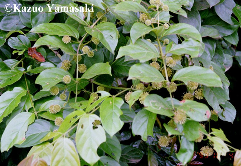